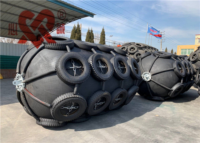
Customized Natural Pneumatic Marine Fender With Chain And Tire Net
The "Yokohama Type Pneumatic Rubber Fender" was developed in 1958. Progress in the development of such floating pneumatic rubber fenders is closely related to the progress and development of ship technology, and has to continuously cope with progressively larger oil tankers such as VLCC's, ULCC's, large gas carriers, bulk carriers and floating structures. Floating pneumatic fenders are used world wide for ship-to-ship (STS) transfer operations, terminals, and for all kinds of ships. Since its creation until today, more than millions of fenders have been supplied worldwide both for ship-to-ship and ship-to-dock (STD) operations serving our valuable customers. These fenders play a critical role in the safe operation of ship berthing and mooring
The structure of Rubber Pneumatic Fenders:
The outer rubber layer protects the cord layer and inner layer from abrasion and other external forces. This compound has sufficient tensile and tear strength to withstand any weather condition and hard usage
The cord layers are arranged at ideal angles to hold the internal pressure and to distribute the stress evenly. The fenders cord layer is constructed by means of integrative twine technology and consists of polyamide fiber with high tensile stress, so that the fenders have unique strength and uniformity in different directions.
The inner rubber layer seals the air inside, utilizing a compound with airtight quality.Pneumatic Rubber fender description Yokohama rubber fender is intended to be used for the berthing and mooring of a ship to another ship or berthing structure. It also specifies the test and inspection procedures for high-pressure floating Pneumatic Rubber Fender.
Flange opening:The metal parts at both ends of fender,to which an air valve or safety valve can be adapted.
Pneumatic Rubber Fenders are suitable for many applications including:
1. Tankers, Gas Carries and Bulk Cargo Ships;
2. Fast ferries and aluminum hulled vessels;
3. Temporary of permanent installations;
4. Rapid response and emergency fendering;
5. As stand-off fenders to realign ships with shore facilities.
Features of pneumatic fender:
* Available in a variety of sizes , Diameters ranging from 500 mm to 4500 mm and length ranging from 500 mm to 12000 mm
* Many kinds of color ,Black , Milky white , Warship Level Gray , Orange Red , Blue
* Contructed with an inner rubber layer,reinforcing cord layers and outer rubber layer
* Comprehensively tested for material and hydrostatic pressure irregularities
* Correctly evaluated for angular and durability performance
* Clearly marked with all relevant identification
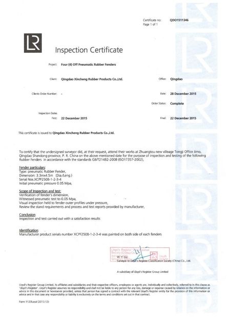
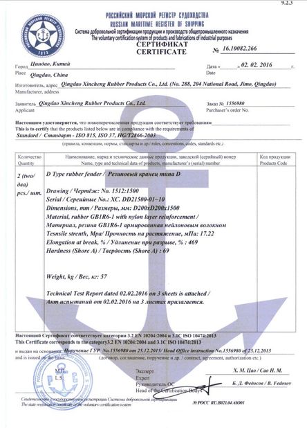
* Complete with up- to -date certification
| Pneumatic 50 fender size and performance requirements |
|
Nominal size diameter x length
mm
|
Initial internal pressure
kPa
|
Guaranteed energy absorption (GEA) |
Reaction force at GEA deflection(R) |
Hull pressure (Internal pressure) at GEA deflection (P) |
| Minimum value at deflection 60±5% kJ |
Tolerance±10 % kN |
Reference value
kPa
|
| 500 x 1000 |
50 |
6 |
64 |
132 |
| 600 x 1000 |
50 |
8 |
74 |
126 |
| 700 x 1500 |
50 |
17 |
137 |
135 |
| 1000 x 1500 |
50 |
32 |
182 |
122 |
| 1000 x 2000 |
50 |
45 |
257 |
132 |
| 1200 x2000 |
50 |
63 |
297 |
126 |
| 1350 x 2500 |
50 |
102 |
427 |
130 |
| 1500 x 3000 |
50 |
153 |
579 |
132 |
| 1700 x 3000 |
50 |
191 |
639 |
128 |
| 2000 x 3500 |
50 |
308 |
875 |
128 |
| 2500 x 4000 |
50 |
663 |
1381 |
137 |
| 2500 x5500 |
50 |
943 |
2019 |
148 |
| 3300 x 4500 |
50 |
1175 |
1884 |
130 |
| 3300 x 6500 |
50 |
1814 |
3015 |
146 |
| 3300 x 10600 |
50 |
3067 |
5257 |
158 |
| 4500 x 9000 |
50 |
4752 |
5747 |
146 |
| 4500 x 12000 |
50 |
6473 |
7984 |
154 |
| Pneumatic 80 fender size and performance requirements |
|
Nominal size diameter x length
mm
|
Initial internal pressure
kPa
|
Guaranteed energy absorption (GEA) |
Reaction force at GEA deflection (R) |
Hull pressure (Internal pressure) at GEA deflection (P) |
| Minimum value at deflection 60±5% kJ |
Tolerance±10% kN |
Reference value
kPa
|
| 500 x 1000 |
80 |
8 |
85 |
174 |
| 600 x 1000 |
80 |
11 |
98 |
166 |
| 700 x 1500 |
80 |
24 |
180 |
177 |
| 1000 x 1500 |
80 |
45 |
239 |
160 |
| 1000 x2000 |
80 |
63 |
338 |
174 |
| 1200 x 2000 |
80 |
88 |
390 |
166 |
| 1350 x 2500 |
80 |
142 |
561 |
170 |
| 1500 x 3000 |
80 |
214 |
761 |
174 |
| 1700 x 3000 |
80 |
267 |
840 |
168 |
| 2000 x 3500 |
80 |
430 |
1150 |
168 |
| 2500 x 4000 |
80 |
925 |
1815 |
180 |
| 2500 x 5500 |
80 |
1317 |
2653 |
195 |
| 3300 x 4500 |
80 |
1640 |
2476 |
171 |
| 3300 x 6500 |
80 |
2532 |
3961 |
191 |
| 3300 x 10600 |
80 |
4281 |
6907 |
208 |
| 4500 x 9000 |
80 |
6633 |
7551 |
192 |
| 4500 x 12000 |
80 |
9037 |
10490 |
202 |


 Your message must be between 20-3,000 characters!
 English